Product Manuals
How to Set Up Lora Gateways
Parts of the Lora Gateway
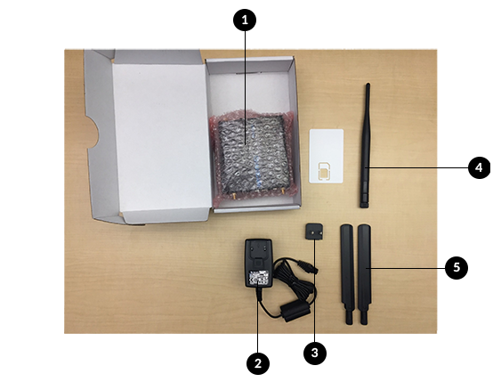
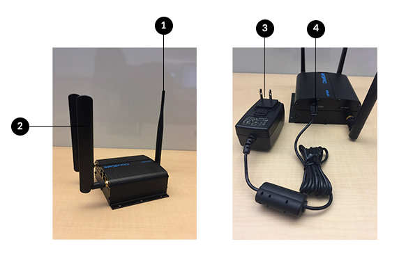
The Lora Gateway consists of:
- Lora Gateway
- Power Box
- Adapter
- RF Antenna
- (2) GSM Antennas
General Rules and Knowledge for Lora
- LoRa stands for Long Range
- It’s low power and low frequency
- Different regions have different frequencies
- The device has the Spread Factor (SF) 7 – 12.
- A spread factor of 7 is a shorter range and more ideal because it uses less battery
- A spread factor of 12 is a longer range that will drain the battery faster
- An ethernet cable is required to connect the Lora gateway to your computer as well as to troubleshoot
- Never press the reset button for more than 30 seconds because it will erase everything
Assembling the Gateway
- Screw in the RF Antenna on the side with one port.
- Screw in both GSM Antennas on the side with two ports.
- Place the straight edge of the adapter in the power box first. Press down on the bottom to lock it in.
- Connect the assembling power cable in the back of the gateway into the associated port.
- After completing these steps, the gateway is physically assembled.
Establishing Power and Connection
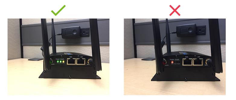
Plug the gateway in. The gateway will boot up and then look for a signal.
- Correct state is that System State is green, WWAN State is green, WWAN Signal is orange
- If System State remains red, there is a failure in the system.
- If WWAN State is red or orange, the gateway failed to connect
